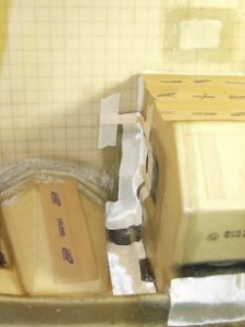
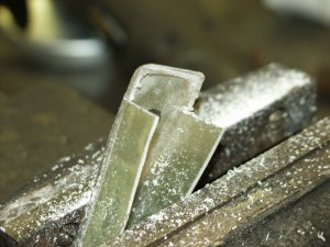
The exhaust tunnel with the BID cloth in place that will become the reinforcement lay-up.
The right side, lower, center engine mount attach point reinforcement foundation..
Well, here we are, starting on the back side of the fire wall again.
I'm rewriting this page in the format of page 9. How well it goes is yet to be determined. It's difficult to rewrite something and still convey the same meaning, but the format in page 9 lends itself much better to the story of "My Glasair III".
2 Hours, June 1, 2003
It's back to the reinforcement lay-ups around the exhaust tunnels after doing the under side of the fuselage (exhaust tunnels and nose gear wheel well). Two layers go on on each tunnel. I marked out the outlines for the exhaust tunnel lays-ups, sanded them thoroughly along with removing a few warts and then fitting the cloth for both lay-ups There were two air bubbles (one on each side in the center, lower engine mount area).
|
The exhaust tunnel with the BID cloth in place that will become the reinforcement lay-up. |
The right side, lower, center engine mount attach point reinforcement foundation.. |
Note the light colored areas in the right side photo. The surface in these areas needs to have a bit more resin added. When using peel ply it works better to use a bit more resin (wet) than when not using peel ply.
Also, note the rough textured area (which is also lighter colored) at the left center. The peel ply did not make contact and left the texture of the glass cloth visible in this area. Again, it should have had a bit of excess resin with the cloth pressed down smoothly. Neither surface is a problem with the next lay-up going over it in a day or two, but when it's the last lay-up the peel ply leaves a surface with a "finished" look, as well as one ready to paint... albeit with the likely hood of a few whiskers.
5 hours, 2 June, 2003
Good progress today. I filled both of the previous listed air bubbles and did both layers of the two layer lay-up shown above. OK, I did the first layer, let it cure, striped off the peel ply and did the second lay-up which is still curing under the peel ply. I finished the second lay-up at 3:00 AM
| The copilot's side, exhaust tunnel with the peel ply in place. Note the resin soaking through the peel ply. | The peel ply has been removed, the lay-up looks entirely different than one done without peel ply. It is smooth and two layers are almost transparent Instead of rough, the edges are smooth and taper down the the surface below. This is the same lay-up seen on the left with the peel ply in place.. |
4 Hours, 3 June, 2003
I also cut three 3 inch wide X 6 foot long, strips of peel ply. I keep them laying in the fuselage and cut off what ever is needed. I have 9 yards of the lighter weight peel ply (Poly Ester), but have not done a test lay-up yet. The medium weight Green, works very well, except for the whiskers it leaves and those have to be removed which is relatively easy. The light weight leaves few whiskers, while it is rare for the heavy weight stuff to leave more than one or two.
3 Hours, 4 June, 2003
I did the first layers of the lay-ups shown below.
| I cut and fitted the first layer of the two layer lay-ups (except the corner) in figure G-34 and the single layer lay-ups in G-35 from the G-III manual. Note the masking paper to catch the "drips" | The detail of the lay-up at the front of the wheel well to fire wall and belly pan as well as the one over the wheel well flange and belly pan. |
The fun part here is making sure I don't miss a page as a good many of the lay-ups must go in order. Again, Note the masking paper. (I should have found this stuff about 6 months ago <sigh>) Note the tongue depressors used to hold the cloth in place.
| The lay-up against the firewall is done, while the side and rear still have the peel ply in place. | The right side (Copilot's) of the nose gear wheel well with the peel ply in place. |
| The rear view of the wheel well to reinforcement rib lay-up with peel ply in place |
The bottom layer of peel ply being removed.
I *generally* cut the peel ply in 2 inch wide strips and then just cut to length. This not only makes them easier to handle, but allows them to better conform to the shapes. This lay-up was covered with 3 pieces of peel ply. One in the center with the top and bottom over laying the center. This gives a good view of the freshly exposed surface and shows how well the new lay-ups blend into the previous lay-ups. |
4 Hours, 5 June, 2003
I cut, fitted, and installed the second layer of the lay-up along the bottom and rear of the nose gear wheel well. Then did both corner lay-ups at the rear of the wheel well
| The contrast between the soaked (and cured) peel ply and the surface after removal. A close examination of the lower area will show the weave of the cloth impressed into the surface of the resin. The surface at the edge of the cloth is smooth and tapers evenly into the previous lay-up. | The rear of the nose gear wheel well and the back of the fuselage reinforcement rib after removing the peel ply. |
| The corner lay-ups between the rear of the nose gear wheel well and the fuselage reinforcement rib. This is the first layer with a second going directly on top. These are made from a 3 inch wide by 3 inch long strip of cloth cut to fold like a box. |
DON'T forget to cut the peel ply on the bias!
Note all the "whiskers" between the top of the peel ply and the resin when I forgot and used a strip cut on the zero bias instead of the 45. Check out this one blown up to full size! |
5 Hours, June 6 through June 17, 2003
It's been sanding, sanding, and more sanding. I'm working in the outside corners of the fuselage where the engine mount reinforcements will be installed. Being the bottom areas are at the low spots the excess resin, drips, and what have you all tended to collect here. Even with the use of the masking paper and using peel ply to help take up the excess resin. Also there are the edges of the belly pan laminate joints to the fuselage sides and the 4 layer lay-ups that hold in the fire wall. These lay-ups were done without the benefit of peel ply and thus have some rough and abrupt edges that require sanding. Add all these together and these areas are taking an inordinate time invested in sanding.
Each corner gets a two layer lay-up that goes from an inch over lap onto the foam on the sides, over the belly pan to fuselage joints and up onto the exhaust tunnels. They also extend from the foam about 8 to 10 inches back all the way to the fire wall and cover the cutouts for the engine mounts with about an inch over lap up onto the fire wall past the cut outs. The photos will show far better than I can describe.
3 Hours, 21 June, 2003
Prep work (sanding and sanding and sanding) as well as fitting the cloth for the lower engine mount reinforcement foundation for the copilot's side.
6 Hours, 22 June, 2003
Prep work (sanding and more sanding) for the lower engine mount reinforcement foundation. I also fitted the cloth for the pilot's side.
8 Hours, 23 June, 2003
I removed the glass cloth from each side and gave the area an Acetone wash. Then I did the first two lay-ups for the bottom engine mount reinforcement foundation covering each lay-up with peel ply. It's getting way too warm to do lay-ups during the day, so I have to wait till it cools off in the evening. The shop is well insulated so it's only been getting to about 77 while it's over 90 outside. OTOH pot life gets pretty short much above 70 F and when the resin begins to gel it sets much more quickly than at 70 which is much more quickly than 68 F.
Hours, 24 June, 2003
Trimming, sanding and then the second lay-up on the copilot's side. I was having a problem getting the cloth to wet thoroughly where it's cut and overlaps in the bottom of the cutout in the firewall. I worked at stippling until the stuff was moving around and I was having to pick up the excess resin and wet the cloth in other areas. Finally I took hold of the top layer of cloth and lifted it. It looked like the layer under wasn't wet so added more resin, but it still didn't look wet enough. So I lifted that piece and .... The area underneath didn't look as if it had been wet enough before curing. At this point I was looking at just a bit more than a little extra work...maybe not too much though...
At this point I removed the wet lay-up and washed all the fresh resin out of the fuselage with Acetone.
Working carefully with a high speed grinder with a sanding drum, I started removing the top layer in the firewall cutout. Sure enough, when I hit the second layer ( where it was cut so it could overlap to fit the material starting flaking off. indicating poor adhesion. I didn't get a photo of the area showing the problem.
When I started the last lay-up the area with insufficient resin was not visible. My guess is it was camouflaged by the texture from the peel ply and sanding so it didn't become visible until it was wet with resin.
This leaves me with a couple of choices. I could remover the entire previous lay-up, but I have no desire to even start removing a lay-up that large. I could remove all of the lay-up in the fire wall area, or I could just remove the dry areas and do a single layer lay-up over that area. As the dry area is a relatively large portion of the firewall cutout, I don't think it'd take me more than an extra hour, or two, to remove all of that lay-up on the firewall which would end up with a much better looking fix. Sooooo... That is my current plan. Stay tuned to see how it actually comes out.
5 Hours, 25 June, 2003
Using the Dremel tool with a 90 degree head and a sanding drum, or rather drums, I carefully removed the two layers from the last lay-up in the firewall recess and the area of the lay-up toward the center of the firewall at the outside edge of the recess.
5 Hours, 26 June, 2003
I cut two pieces of cloth to extend about an inch beyond the beveled areas of the recess in the fire wall. These pieces also extended onto the belly pan and sides just shy of an inch.
|
Fitting the pilot's side lay-up for the engine mount reinforcement |
The installed lay-up with peel ply in place described below |
4 Hours, 27 June, 2003
I did the first lay-up and covered it thoroughly with peel ply. I added the heat from the halogen lamps to speed the process. later in the evening I removed the peel ply and did the second lay-up, but without the heat.
|
Right: Photo of the Halogen lights used as heat lamps. Note fuselage is inverted with the reinforcement rib at the top. |
4 Hours, 28 June, 2003
I removed the peel ply from the work done yesterday. Then, I fitted the cloth for the top lay-up on the pilot's side as well as sanding the corresponding area on the copilot's side
4 Hours, 29 June, 2003
I fitted the copilot's side top lay-up and cut strips of peel ply from both the coarse and medium weight polyester to use on the top lay-ups.
3 Hours, 30 June, 2003
Oops! I forgot to wash the surface on which the lay-up is to be done with acetone, so I removed the cloth from each side and thoroughly washed each side.. Then replaced and repositioned the cloth.
2 Hours, 01 July, 2003
I ended up working on the mower deck this afternoon, but did the first lay-ups on each side.
I also installed a small air conditioner in the west shop window. It's not really big enough, but it takes the humidity down into the 40% range and keeps the temperature in the low 70s even on "low cool". I think if I left it on high cool over night it would actually be a bit chilly in there. As it is, with the low humidity and 72 F I am getting pot life long enough on 100 gram batches to do the large lay-ups for the foundation of the engine mount reinforcements and lay up the peel ply without any sign that the mix is beginning to gel. It does soon after I finish though.
3 Hours, 04 July, 2003
I filled several voids and then did the second and final of two lay-ups for the foundation for the engine mount reinforcements.
Unfortunately yard and home chores have kept me busy through most of July. Such things as rebuilding the lawn mower deck and getting the big 9 KW generator hooked up to power the house when the power was out for some time due to some strong storms.
2 Hours, 25 July, 2003
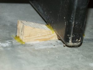
| The engine mount was slid into place and held by a 2 X 4 clamped across the front. The waterline 100 marks were made more prominent by using Orange Duct tape. The wood blocks provide a mount for the long level when leveling the fuselage from side-to-side. |
Note pieces of tongue depressors used to shim engine mount into position. |
|
The mount was leveled by inserting a rod through the nose gear mount and placing a torpedo level on the rod. I couldn't get the level to stay balanced so I couldn't get a picture of that. |
Bill Albe turned out a couple of these drill guides on his lathe for me. The larger of the two (shown above) fits the 4 corners of the engine mount |
|
Left:
The smaller drill guide fits the lower, center engine mount attach points. I use the 90 degree head on the Dremel tool to drill the pilot holes through those. |
2 Hours, 26 July, 2003
I did a two layer lay-up under the lower center engine mount pads. These lay-ups are spacers to provide support for the pads. There is a 3/8ths inch Aluminum spacer that goes between the lay-ups and the engine mount pads.
|
The sanded area for the spacer lay-ups Note the clamp which is used to hold the engine mount |
The pilot's side area and the faint outline for the lay-up (red) |
Two, two layer lay-ups complete with peel ply. |
1 Hour, 27 July, 2003
After removing the peel ply and fitting the engine mount, it appears I need to do three more lay-ups under each pad. I also re-drilled the pilot holes for the lower center engine mounts.
5 Hours, 28 July, 2003
I did 3 more lay-ups for the lower center engine mount pads. Then I shifted to the basement, remarked the rib positions in the upper and lower horizontal stabilizer shells. Removed the shear web, took it and the ribs out to the shop and trimmed the ribs to fit the shear web.
|
Right: The five layer lay-up for fill under the lower center engine mounts. |
4 Hours, 31 July, 2003
I marked the rib positions, removed the rear shearweb, and took the horizontal stab shell that had been jigged out to the shop. I sanded the rib and shearweb areas, cleaned them and then washed those surfaces with acetone. I also scribed the cord line all the way across both shells and assembled a 4 foot long block sander. The ribs have been trimmed and fitted to the shear web.
|
Cutting and trimming the ribs to fit the shear web |
First, the cross cut |
Then trim the back |
|
The "A" (end) Rib shaped to fit the shear web |
The ribs have a close enough fit to stand alone in the Shear Web |
The four foot long sanding block waiting for a coat of Poly-Urethane |
5 Hours, 1 August, 2003
What a night! I brought the Upper shell (the one that is jigged) back into the basement. I have block sanded the rear edges and they match the cord line to less than 1/16th inch. Unfortunately while block sanding the jigged shell it broke loose. I mixed up some Bondo and stuck the position blocks back down. I was able to "almost" finish block sanding the trailing edge before it broke loose again.
|
Left: The jigged upper panel with the shear web and ribs in place. |
There must have been a reason I used furniture polish to clean that desk oh so many months ago, but I don't remember why. I now know it makes a good release agent. It's probably good that the shell broke out of the fixture. I noticed that one of the desks (shown at the right in the photo above) had moved a bit so I started the leveling procedure all over again. Unfortunately I spent nearly 2 hours chasing the level. The desks are independent and not only have to be level, but match each other in height. The north one went into position easily, but the south one is unstable and keeps moving. I have them nearly level, but gave up for the night.
These are those old, big, heavy wood government style desks. Although they look identical, they aren't. One is taller than the other. The work surface has to be flat and level. Unfortunately the bases of the desks set in a good foot or more from the ends so when you shim up one end, the other goes down. It kinda works the same diagonally too.
I'm tempted to clean off east end of the work bench in the shop and use it instead of the desks in the basement. It would be a bit awkward changing, but as I have to completely re-level the work surface in the basement and then re-jig the top shell it shouldn't be any more work. That, and it would be handier to work on the stab out in the shop...and it won't smell up the whole house from the Vinyl Ester Resin. What should have taken about two hours has already added up to 8 and it may be double that by the time I finish the block sanding of the rear edges of the stab shells.
4 Hours, 2 August, 2003
Some times it's just good to take a break. I went down to look over the desks and fixture this morning. After studying them for a couple of minutes, it took about five minutes to level the whole works. Then another 20 minutes to "hot glue" the leveling wedges to the floor and the desks to the wedges. I'm rebuilding the jig for the horizontal stabilizer and I still have some block sanding to do on the trailing edge of the (un-jigged) shell.
|
One view of the leveling wedge hot glued in place |
Another wedge hot glued in place. The marks from the previous position are easily visible. |
Soooo... Instead of having the horizontal stabilizer closed by the time Joyce got home from her bicycle tour, I have it back to looking about like it did when she left.
If you have comments or suggestions on Content or spelling, (Proofreaders welcome) email me at webmaster@rogerhalstead.com
| Start | Previous Page | Next Page | Back to Roger Halstead's Home page |