Last Updated: 22 December 2005
1023 Hours total to start of page
This is probably as good a place as any to start a new page as I'm moving on into the elevator construction although I would like to make page 11 a little smaller for down load time.
March 25
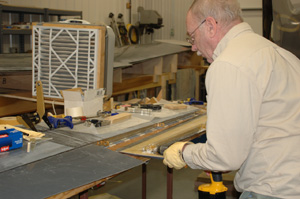
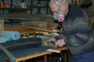
Today is cleaning day so far. There is a tremendous amount a dust accumulating in the shop from all the sanding as well as what tracks in So, I opened the big doors at each end of the shop with a good stiff wind blowing in the big front doors. With the aid of an air hose attached to an 80 gallon compressor I gave things a good going over and let mother nature clean up the dust. Even so I still was wearing a respirator and my glasses were a bit darker than usual when I finished.
I really need to go in and do a good house cleaning, throwing out all the old *treasures* that I'll never need until the day after the trash pickup. Once I find the floor then I can start some real serious cleaning.
Backing up a bit:
5 Hours March 22
I set the stabilizer up in the foam supports used earlier. This puts the trailing edge up and in a good solid position. Using a drill stop on a 1/4" drill bit I drilled out all the hinge bolt holes that are plugged with the red clay. Then, using a long deck #10 deck screw, I carefully picked the clay out of all 12 bolt holes and nuts.
(Much of this is the same procedure shown on page 11 with photos)
At this point I made what was a rather unsettling discovery. At the center of the trailing edge the un-jigged shell is slightly less than 3/23" closer to the hinge centerline than the jigged shell. They are symmetrical and the edges are about as straight as I can get them. I lightly block sanded the upper surface and the differences are less than the thickness of the gel coat.
Using a smaller block I sanded a 45 degree bevel on the inside corner of both the top and bottom trailing edges of the stabilizer shells. The thickness is uniform as far as I can see.
4 Hours March 23
I reinstalled the hinges, cut the shear web to fit, cut the end rib to fit the end of the shear web, sanded the edges of the elevator shells to get rid of the mold lips and to give them the same shape.
WARNING: I am going back to page 11 and add a warning. The manual gives dimensions to cut off the shear web. These can be off as much as a half inch or even more and they may be *short*. To my way of thinking: The outer end should be cut to fit the bevel at the end of the elevator. THEN the inside end should be cut to give the proper distance from the horizontal stabilizer center line.
5 Hours March 24
I blocked up one end of the stabilizer which put the other side flat on the work table. I then fitted the shear web, end rib and bottom panel into place. I used 5 layers of masking tape on the 45 degree beveled edge to get the approximate 0.025" spacing between the elevator and stabilizer. It took *many* fittings and even though weighted and lightly clamped the stabilizer kept moving as the clearance for the outboard hinge was tight. I finally added a bit more clearance for the end hinges and it all seems to fit together properly.
The hinge seems to work well temporarily hot glued together so it's about time to bond the shear web and hinges to the elevator shells.
2 Hours March 25
I prep sanded the left side elevator shear web and trimmed the end rib... plus more fitting.
2 Hours March 26
More sanding and fitting. I also located and set up the actuator end plates and linkage.
I don't like the flexibility of the hollow core door for the work bench so I'm going to move the stab to either the cutting bench in the shop, or to the top of the old office desk in the basement for the rest of the elevator fitting and lay-up work. It bothers me to see things move one place when I press some where else.
7 Hours March 27
Much as I said about moving the stab, things seemed to fit right so I went ahead and bonded the shear web in the left elevator shell (as jigged). After cure and trimming I hot glued the hinges in place, removed the hinge pins, turned the elevator shell around, and drilled the holes for the hinge bolts and temporarily bolted the hinges to the shear web. I had to revise my time as I realized it was 4:30 AM when I came in from the shop.
Now for the right side.
2 Hours March 28
I fitted the right side elevator shell, attached the elevator side of the hinges to the stab, trimmed the inside of the counterweight arm, trimmed the end of the stab to match the counterweight arm, and fitted the shear web.
2 Hours March 29
I added the spacers (5 layers of masking tape) to get the spacing between the right elevator shell and the stabilizer. I also did a bit more trimming on the shell and stab.
2 Hours March 30
|
|
|
|
|
|
|
|
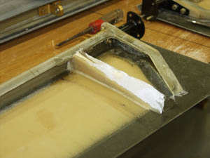
I sanded the shear web and surfaces on the inside of the jigged elevator shell. Then mixed up a 55 gram batch of resin, mill fiber, and Cabosil and used it to bond the shear web in place. I clamped the hinges to the face of the shear web and weighted the shear web to hold it in place. I clamped the elevator shell to the work table.
 |
 |
 |
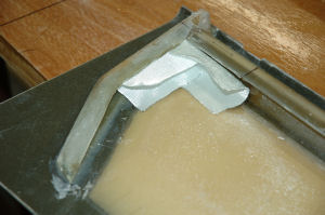
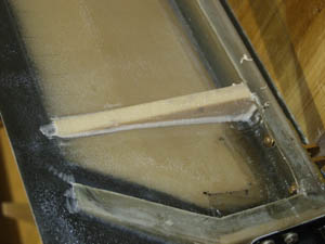
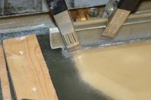
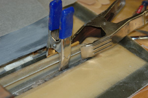
| Shear web in place | Clamps and weights for shear web | Another view of same |
3 Hours March 31
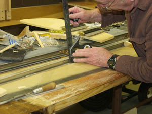
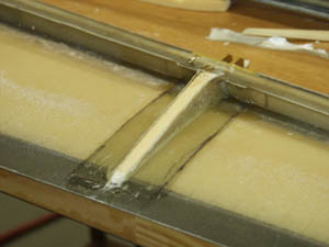
Removed the weights, hot glued hinges to shear web. removed clamps, and turned panel around. I used the holes in the hinges as guides for drilling the holes in the shear web for the hinge attach bolts, then trimmed off the hot glue. Using a high speed grinder I trimmed the leading edge of the elevator panel to clear the hinges and block sanded both the leading and trailing edges.
|
|
|
|
|
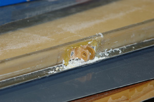
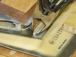
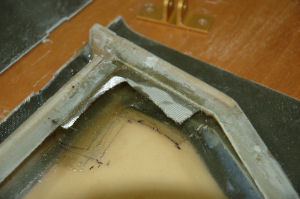
Using Hinge for drilling template Note tape on bottom trailing edge of stabilizer |
Hinge hot glued in place with holes drilled |
Hinge temporarily bolted on shear web |
I made a three layer lay-up to be used as shims when fitting the elevator torque tubes.
The horizontal stabilizer is now set up in the fixture that was used for its assembly. The lower elevator shells are fastened to the hinges with the trailing edges blocked up and even.
|
|
|
|
|
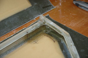
Clamp holding end hinge to shear web |
Hinge hot glued to shear web |
Drilling bolt holes using holes in hinges as guides - Note tape spacers on stab |
The elevator actuator arm was used as a template to create a temporary spacer 2 X 2 1/2 inches and a 1/4 inch thick. This is used during assembly instead of the actuator arm as the arm will not clear the assembly fixture. The arm was used as a template for drilling the 4 holes matching the torque tube ends by clamping the arm down on top of the spacer.
4 hours April 09
I trimmed about a half inch off the inboard end of each lower elevator shell. This gives about an inch space between them and is just enough to clear the center of the torque tube assembly. I fitted the Elevator torque tubes to the end rigs.
|
|
|
|
Trimming upper elevator shell to length using high speed abrasive wheel |
Locating center line for torque tube assembly |
At this point I departed from the manual a bit. With the elevator end ribs clamped in place I used the end plates on the torque tubes as a template to drill the mounting holes. The three layer laminate was cut to the shape of the end plates.
3 Hours, April 10
With the torque tube assembly and spacer I bolted the elevator end ribs to the torque tube assembly and fitted the end ribs. I removed the end ribs and prep sanded them inside and out, plus the matching surfaces on the jigged elevator shells and gave the rib surfaces an Acetone wash. I then mixed up a batch of resin with mill fiber and some Cabosil. As with the shear web I built up a bead the length of both end ribs. I then fitted the ribs (still attached tot he torque tube assembly) in place and weighted them down.
|
|
|
|
|
Bonding end ribs - Wood strips hold panel flat Level insures panels are at the same height. |
Bricks on boards laid over end ribs to a good bond |
Torque tube assembly bolted to end ribs. |
4 Hours April 11
I removed the torque assembly from the end ribs, then trimmed away the excess mill fiber. I mixed a small batch of mill fiber and Cabosil to fill the gaps between the end ribs and shear web as well as building up a radius edge at the end rib and elevator shell junction.
I cut eight, 2 1/2 inch by 6 inch pieces of cloth on the 45 degree bias. I installed on on the outboard edge of the end rib and lapped it around onto the back of the shear web to a distance of 3 inches from the inside edge of the end rib. I trimmed the excess cloth in the green state and filled several voids. I then added a second lay-up over the first. This will be a 4 layer reinforcement.
3 Hours April 12
|
|
|
|
|
Fitting reinforcement lay-ups at end rib to shear web |
Reinforcement lay-up in place |
Four reinforcement layers that have been trimmed |
I finished up the elevator end rib to shear web reinforcements with two lay-ups on each assembly. I also did some trimming to get the end of the un-jigged shell to fit better at the end hinges.
3 Hours April 27
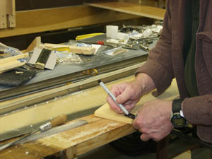
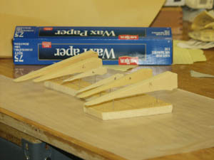
Using a ruler I measured the dimensions for the ribs and then cut out the triangular shapes from 1/2" foam. I used 1/4" foam for the small end ribs. Note: There are no elevator rib templates, you are on your own for figuring out how to make them. This is the route I followed.
|
|
|
|
|
Measuring depth of shear-web |
test
Measuring height of shear-web |
Marking initial triangular shape of rib. |
3 Hours April 28
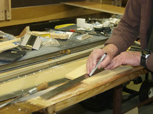
Using an adjustable template I transferred the shape of the jigged panel to one side of each rib. I finished shaping the ribs to fit both elevator shells.
|
|
|
|
|
Drawing rib outline on foam |
Drawing second outline on foam |
Outlines on foam |
|
|
|
|
|
Using adjustable template to get shape of skin |
Triangular rib setting in place |
Notching rib to fit in shear-web. |
4 Hours April 29
Coated elevator ribs with a thin Q-cell mix to seal them. After cure I trimmed off the excess. Realigned the middle elevator hinge on the left jigged panel.
|
|
|
|
|
Ribs, shaped, marked and set up for sealing |
Rib in place with Q-Cell radius |
Cloth for rib reinforcement |
2 Hours April 30
Hot glued the elevator hinges in place and then removed the bolts. I used a thick Q-cell mix to bond ribs left jigged elevator shell
5 Hours May 01
Trimmed, cured Q-Cell mix and radius around elevator ribs. Cut and fitted two elevator rib reinforcements. Trimmed reinforcements in the green state and then added the second reinforcement for each rib.
|
|
|
|
|
Rib with cloth layer on each side |
Lay-ups ready for trimming |
Trimmed lay-ups on rib |
Using the thick Q-Cell mix I installed all three ribs in the left (jigged) elevator shell. The mix around the edges of the ribs was shaped to a 3/8" radius. I also used a thick Q-Cell mix to radius the joint between the front of the shear web and the elevator shell that is attached (both sides) with the exception of the areas under the hinges.
4 Hours May 02
I trimmed the elevator rib reinforcements on the left side, then did both lay-ups on the right side, trimming while each layer was in the green state.
2 Hours May 03
Worked on a more precise alignment of the elevator hinges and the torque tubes.
1 Hour May 04
Ordered the new, tighter fitting elevator hinge bushing inserts, one elevator hinge bracket, and some assorted washers.
1 Hour May 05
Using the adjustable template I transferred the shape of the left side un-jigged shell to the ribs, then used a small drum sander to do the shaping. I did have to deepen the hinge notch on the un-jigged shell, but that area will end up being cut out to give access to the hinges and hinge pins after the elevators are closed.
I'm basically waiting for the new bushings before finishing up the alignment.
September 19, 2005
Here it is past mid September. Yes, I am still making progress, but I did take a break over most of the summer and I do have to get my diary up-to-date.
More photos coming soon (They're in the camera)
3 Hours 21 September
Using spirit level on the engine mount I leveled the fuselage laterally (side-to-side) and set the water line 100 level using the laser level. This took a bit of work as the water line 100 was marked a 1/4 inch low on the port side. Every thing is now within about 1/16" with the engine mount level.
4 Hours 23 September
Using laser level I marked the water line 100 on both sides of the fuselage using tape for a marker.
I marked out the cut out for the horizontal stabilizer on the port (Pilot's)
side as the factory had it about 3 inches low.
The one on the copilot's side was properly located with the cord line 8 1/2
inches above the water line 100.
4 Hours 25 September
Cut out openings in empennage for horizontal stabilizer.
4 Hours 27 September
Fitted horizontal stab to cut outs in fuselage. Added a coat of fill using mill fibers and Cabosil to the leading edge of the horizontal stabilizer.
4 Hours 28 September
Block sanded leading edge of horizontal stab.
4 Hours 30 September
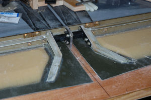
Fitted inboard and center hinges, then bonded them to the shear web.
3 Hours October 1
Finished fitting and bonding hinges in left side elevator (as jigged)
2 Hours October 2
Bonded the inboard and center hinge for the right side elevator (as jigged)
3 Hours October 3
Finished bonding the hinges to the elevator shear web.
3 Hours October 4
Block sanded on the leading edges of the elevator shells. I'm relieving the "up elevator" leading edge so it will bottom out on the hinge brackets at 30 degrees up. It "should" hit the trailing edge of the horizontal stabilizer just prior to the 30 degrees. The lower shells, which are not bonded yet, are getting the hinge access cut outs made. I'm also finding some small spots where the elevator ribs still need trimming. There is a lot of sanding left before every thing lines up. I am getting tired of block sanding! NO, that's not correct. I've been tired of block sanding for the past couple of years.
NOTE: Knowing what I know now, when bonding the shear web in the horizontal stab and closing the horizontal stab I'd use thicker spacers so the trailing edge of the stab would be about 3/32" thicker instead of trying to keep it as thin as possible. This would make the alignment of the elevator much easier. It would also allow the ends of the elevator to be slightly thicker and make it easier to install the end hinges.
Although the jigged elevator shells are straight, the shear web is not. (Not bad, but not straight either) This leaves the center hinge on the left elevator (as jigged) noticeably off center, but in line with the other hinges. Once the elevator is closed and the shell kept straight this "off center" appearance will disappear.
Another area where the work will differ from the manual, or at least the older manual is the reinforcement of the shear-web and leading edges of the elevators. The old manual uses a "seam tape" while currently they use BID on the 45 in this area. BID is far easier to work with and the old instructions with the 2" seam tape being installed on the jigged panel before closing don't work as stated and require some creative placement. Once the leading edges of the elevator shells are properly trimmed it is easier to just install the two layers of BID cloth after closing. That is not to say the installation is easy as you have to insert the cloth through the relatively narrow opening and it takes a bit of extra care.
4 Hours October 5
Block sanded the leading edges of the jigged elevator shells. I'm aiming for 30 degrees up elevator. The stabilizer is jigged upside down so down is up. I noted some binding in the end (outboard) hinge on the left side (as jigged) starting around 15 degrees. At 15 degrees I couldn't pull the pin out and at 20 degrees I could feel it in the elevator movement. It appears I need to space the elevator side of the hinge forward slightly. BTW, taking enough off the leading edge so it bottoms out against the hinges at 30 degrees is a LOT of material, particularly when you are sanding it off. I'm going to need to replace some of the material taken off the leading edge of the left elevator (as jigged)
I also marked the preliminary un-jigged shell cutouts so I'll be able to get at the elevator hinges.
Additional NOTE: The manual has you remove enough material to limit the elevator up and down travel. This is not what limits the elevator travel! That will be set later on with stops for the bell-crank. It looks to me as if you need about 1/16" of uniform clearance between the elevator's leading edges and the trailing edges of the horizontal stab AFTER you have established the 30 degrees up and 18 degrees down. You need at least the 1/16" clearance to allow for paint on the elevator and on the horizontal stab.
4 Hours October 14
Block sanded the leading edge of the elevator shells on both sides.
4 hours October 15
More block sanding to get the limit of the elevator travel top and bottom
4 Hours, October 16
Prepped the shear web for the left elevator (as jigged) and hinge surfaces, then bonded the hinges to the shear web.
4 Hours October 17
Prepped the shear web for the right elevator (as jigged) and hinge surfaces, then bonded the hinges to the shear web.
4 Hours October 18
Bonded the elevator hinges to the right side as jigged
3 Hours October 19
Removed the right side elevator (as jigged) and removed the hinges. Sanded and prepped the surface, then added a single layer of cloth and resin under each hinge position.
3 Hours October 20
Trimmed the cloth lay-ups on the elevator, opened the holes for the hinge bolts and temporarily mounted the hinges. The elevator now moves freely throughout its present range, although the trailing edge of the horizontal stab needs additional trimming.
4 Hours October 21
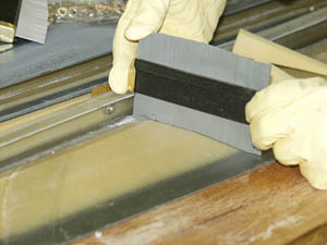
Removed the horizontal stab from the table and moved the rear supports for the stab to the rear edge of the support table. Marked the centerline on each end of the shear web and leveled the cord line of the stab. I then block sanded both the upper and lower 45 degree bevels on the trailing edges. I flipped the stab over to do the top side.
|
|
|
|
|
Block Sanding Trailing Edge of Horizontal Stab |
Checking alignment of upper and lower edges |
Fitting elevator for another try |
3 Hours October 23
Still more sanding on the trailing edges of the horizontal stab.
3 Hours October 24
Removed hinges from the horizontal stabilizer and block sanded on the 45 degree bevel to get more clearance. The elevators with the top shells (as jigged) in place have smooth movement with no binding, but I still need to add about 1/16" more for clearance after the elevator and stab have been painted. I also did some additional sanding on the middle elevator rib to get the upper shell/skin (as jigged) flat.
"I think" both sides are now about ready to close once the access cut outs are properly sized and finished.
1173 Total Hours to date!
3 Hours October 25
Well, twas one of those days. I discovered I had taken a bit too much off the leading edges of the elevator skins. Fortunately it's basically cosmetic and relatively easy to remedy, just a bit aggravating. I have to add between 1/8" and 1/4" to the top (currently jigged) skins so when they are at their extreme travel the gap between the elevator skin and the trailing edge of the horizontal stab will not display the end of the leading edge of the elevator skin. Of course the goal is to have the gap the same width all the way across as well.
I removed the hinges from the left side elevator shear web (as jigged), sanded the hinge areas smooth, then sanded the leading edge of the shear web and elevator skin forward of the shear web. I then fitted the reinforcement for the jigged skin and shear web. The uses the thickness of the reinforcement as a spacer, or shim under the hinge giving about an additional 1/32" of space between the elevator and horizontal stab. It also is correcting a slight asymmetric condition between the elevator and stabilizer as the elevator is run from extreme up to extreme down.
There are a lot of these "finer points" they don't bother to tell you in the construction manual. However I would like to point out the construction manuals for the G-III are one of the most thorough sets I've seen.
3 Hours October 26
Filled the gap on the upper side of the reinforcement installed yesterday with a medium mills fiber and Cabosil mix so its shape conforms to a continuation of the elevator skin.
4 Hours October 27
Block sanded the mill fiber mix on the leading edge of the elevator skin to the proper shape, cut notches for the hinges, reinstalled the hinges, and fitted the skin to the horizontal stabilizer. So far it moves freely and the gaps look good even at the extremes of the elevator movements.
3 Hours October 28
Removed the right side elevator skin from the stabilizer, removed the hinges and sanded the areas where the hinges had been removed. The next step was to prep sand the entire forward side of the shear web and inside of the elevator skin forward of the shear web. The Gel coat was sanded off from the leading edge back about half an inch.
4 Hours October 31
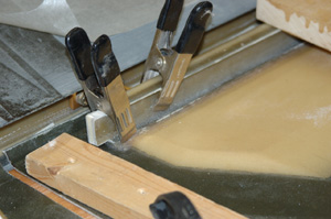
I cleaned the forward side of the shear web and elevator skin forward of the shear web with acetone. Then cut and fitted a length of BID cut on the 45 to the forward face of the shear web, inside of the elevator skin forward of the shear web in a manner so the cloth extends about 3/8" forward of the current leading edge of the elevator skin in a continuation of the forward curve. After this forward extension was almost to the green state, a layer of wax paper and tape was added to hold the proper shape of the curve while the cloth and resin finished curing.
1187 Hours as of Oct 31
5 Hours December 1
I have been working on the G-III right along and have a bunch of photos so I have a lot of catching up to do with this diary between the end of October and the first of December. That covers a lot of hours. Probably enough to put me close to, or over the 1300 mark. I'm going to start another page soon as this one is going to be very large when I get the photos us. I may have to split it.
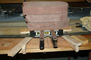
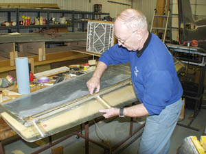
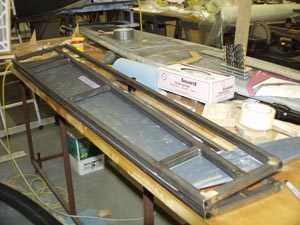
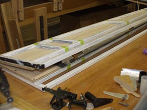
I'm still working on the elevators and decided to build a fixture to hold the shells flat and straight. I use a lot of steel in my work as it's very difficult to get wood to hold its shape in a heated building and particularly with the low humidity. Although I'll have to go back for the details, I have the preliminary elevator travel set. and the right side (as jigged) is ready to close with the exception of a bit of trimming on the ribs to get it to lay flat. I haven't checked the other side yet, but I believe it is closer to closing than the right side.
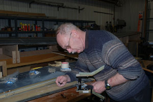
3 Hours, December 22
|
|
|
|
|
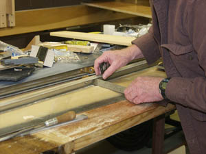
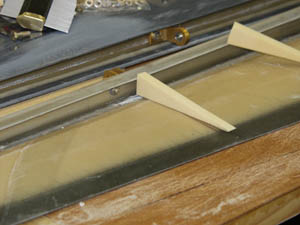
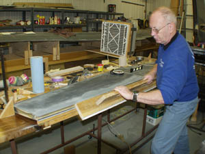
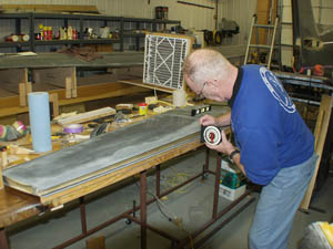
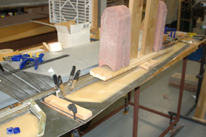
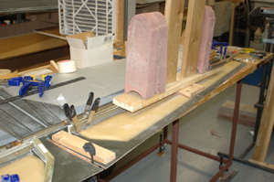
Steel frames showing rib position |
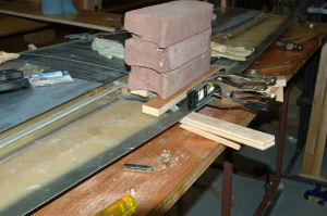
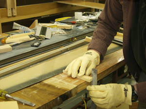
Fixture with wood surface & installed on elevator |
Uncooperative Elevator shell |
The right side elevator shells (as jigged) shown on the left have a high spot some where that will not let the leading edge and trailing edges both match up at the same time. The left side shells shown in the finished fixture (center) seem to match up fine. Note the green tape which lines up with each rib in the fixture and in the elevator. The uncooperative elevator shell is show out of the fixture on the right, but not much detail is visible.
This page has become very large and when the rest of the images are added, I may move part of it to page 13
| Start | Previous Page | Next Page | Back to Roger Halstead's Home page |
If you have comments, suggestions, or corrections email me at
Support
Since starting at 02-Mar-1996 The
![]() says you are caller
says you are caller